- Tensorflow Lite
https://www.youtube.com/watch?v=aimSGOAUI8Y - Classifier https://github.com/gsurma/image_classifier?source=post_page—–4e9af21ae7a8—–
- https://github.com/EdjeElectronics/TensorFlow-Object-Detection-on-the-Raspberry-Pi/blob/master/Pet_detector.py
- https://blog.adafruit.com/2019/09/06/opencv-stream-video-to-web-browser-html-page-raspberry_pi-piday-raspberrypi/
- Check out line 185 of Pet_detector.py . That line says „if a cat, dog, or teddy bear is detected: do this“. You can add more classes to that line if you want to your script to react to more objects. Good luck! https://github.com/EdjeElectronics/TensorFlow-Object-Detection-on-the-Raspberry-Pi/blob/master/Pet_detector.py
C#
- Neues Projekt erstellen, Konsolenanwendung
- easycomapi.cs muss da wohl auch reingelegt werden
- Code löschen, eigenen einfügen
- Debug/Compilieren
- ausführen
- Im Prjektordner release muss die moeller-dll liegen
Power Leader Video
https://gist.github.com/gabonator/3d2bc36e9eb62c52742d45113126c1ba
Device Manager
https://download.xm030.cn/d/MDAwMDA2NTQ=
OpenWRT?
http://mark4h.blogspot.com/2017/07/hi3518-camera-module-part-1-replacing.html?m=1
Model Name: PLV:NC617RW
2020-02-19
https://github.com/futomi/node-onvif
https://github.com/bartbutenaers/node-red-contrib-onvif-nodes
- nc 192.168.1.10 9527
- admin, Passwort leer
- help -> shell -> busybox
- cat /etc/passwd
- busybox
- vi leider nicht da
- nfs
netstart -tulpn
Proto Recv-Q Send-Q Local Address Foreign Address State PID/Program name
tcp 0 0 0.0.0.0:34567 0.0.0.0:* LISTEN 267/Sofia
tcp 0 0 0.0.0.0:554 0.0.0.0:* LISTEN 267/Sofia
tcp 0 0 0.0.0.0:80 0.0.0.0:* LISTEN 267/Sofia
tcp 0 0 0.0.0.0:9527 0.0.0.0:* LISTEN 247/dvrHelper
tcp 0 0 0.0.0.0:9530 0.0.0.0:* LISTEN 241/macGuarder
netstat: /proc/net/tcp6: No such file or directory
udp 0 0 0.0.0.0:36869 0.0.0.0:* 360/sh
udp 0 0 0.0.0.0:34568 0.0.0.0:* 267/Sofia
udp 0 0 255.255.255.255:34569 0.0.0.0:* 242/searchIp
udp 0 672 0.0.0.0:52249 0.0.0.0:* 267/Sofia
udp 0 0 0.0.0.0:67 0.0.0.0:* 317/udhcpd
udp 0 0 0.0.0.0:32845 0.0.0.0:* 267/Sofia
udp 0 0 0.0.0.0:55752 0.0.0.0:* 360/sh
udp 0 0 0.0.0.0:43773 0.0.0.0:* 267/Sofia
udp 0 0 0.0.0.0:45565 0.0.0.0:* 267/Sofia
~
mount
rootfs on / type rootfs (rw)
/dev/root on / type cramfs (ro,relatime)
devtmpfs on /dev type devtmpfs (rw,relatime,size=30536k,nr_inodes=7634,mode=755)
tmpfs on /dev type tmpfs (rw,relatime,mode=755)
tmpfs on /var type tmpfs (rw,relatime,mode=755)
/dev/sys on /sys type sysfs (rw,relatime)
none on /proc type proc (rw,relatime)
devpts on /dev/pts type devpts (rw,relatime,mode=600)
tmpfs on /dev/shm type tmpfs (rw,relatime,size=20480k)
/dev/mtdblock2 on /usr type cramfs (ro,relatime)
/dev/mtdblock3 on /mnt/web type cramfs (ro,relatime)
/dev/mtdblock4 on /mnt/custom type cramfs (ro,relatime)
/dev/mtdblock5 on /mnt/mtd type jffs2 (rw,relatime)
/dev/mem2 on /utils type ramfs (rw,relatime)
Camerashot-URL
192.168.1.10/webcapture.jpg?command=snap&channel=1
https://forum.iobroker.net/topic/17480/steinel-l600-cam/184?lang=en-GB&page=1
VLC kann den Stream oeffnen mit:
rtsp://192.168.1.10/user=admin_password=irgendeinpasswort_channel=0_stream=1.sdp
2020-02-19 Folgende Adresse geht, kein Passwort:
rtsp://192.168.1.1o:554/user=admin&password=&channel=1&stream=0.sdp
https://github.com/tothi/pwn-hisilicon-dvr
Kamera hat immer (?) die 192.168.1.10, auch nach reset kein dhcpdiscover
Software: https://onedrive.live.com/?authkey=!ACy_Xkqe5UcSB1A&id=7F76648DD5B816EE!128&cid=7F76648DD5B816EE
CMS und Device Manager funktionieren unter Windows, damit sind auch die IPs aenderbar, alles in Butter. Software fuer Linux suche ich noch, ausser VLC klappt noch nix. Die Kamerasteuerung klappt nicht unter Linux.
Die Cloud ist mir zu unsicher.
Direktverbindung klappt ueber Adhoc-Netzwerk SSID xjm….
xmeye-App für Android auf Direktverbindung 192.168.2.1
Probleme: app stürzt ab
Zoneminder könnte helfen:
https://zoneminder.readthedocs.io/en/latest/installationguide/debian.html#easy-way-debian-stretch
IoT-Unterricht
Basis ESP8266
- Download und Einpflegen den oT
Installation EasyIoT-Server
- http://iot-playground.com/blog/2-uncategorised/3-easyiot-server-installation
- Webseite
Username: adminPassword:test
Pi mit Touchdisplay SKU: AC-TFT32-V4.1
Edith 20.11.2016
Im DietPi-Image sind bereits die Treiber für dieses Display eingepflegt und lassen sich ueber dietpi-config einrichten, das ganze Gewese ist nicht mehr notwendig.
SKU: AC-TFT32-V4.1
Anleitung hier:
Circuit Basics
Arduino, Raspberry Pi, and DIY Electronics Articles and Tutorials
How to Setup an LCD Touchscreen on the Raspberry Pi
In this tutorial, I will walk you through the process of installing an LCD touchscreen on the Raspberry Pi, step by step. Many LCD touchscreens for the Raspberry Pi include an image file that you can write to your SD card and get up and running pretty quickly. But what if you want to run a clean version of Raspbian, without all the bloatware included on the manufacturer’s image? Also, what if you want to install a different OS such as Rasbmc or XBMC? In these cases, you should follow this tutorial and go through the steps to configure it on your own. This works on the Raspberry Pi 2 Model B as well as older versions of the Raspberry Pi. Don’t worry, it’s not that hard!
I am using the Waveshare 3.2″ TFT (thin-film transistor) LCD. Many other LCD screens are supported by this process, but check here to see if your screen is supported by the FBTFT driver to make sure. Scroll down the file and look for an abbreviated name of the screen you are using:
What we need to do to get the LCD working is install and configure the FBTFT drivers created by notro. There are two types of drivers we need to be concerned with here. One set of drivers is for the actual LCD display screen, and the other set of drivers is for the touchscreen sensors. Here is a good article explaining Linux kernel modules, devices, and drivers, which you may want to read for some background information. The standard version of Raspbian does not include the drivers for LCD touchscreens, so we will need to install and configure them manually. So just follow the steps below to get your LCD touch screen working on the Raspberry Pi.
Touchscreen Setup and Configuration
1. First we need to configure the fbturbo video driver to output the display of the Raspberry Pi to the SPI bus instead of the HDMI bus. At the command prompt, enter: sudo nano /usr/share/X11/xorg.conf.d/99-fbturbo.conf
In this file, find the line that says: Option “fbdev” “/dev/fb0″ and change the fb0 to fb1:
The fb0 option tells the video driver to output to HDMI, and the fb1 option tells it to output to the LCD screen. The file should now look like this:
Press Ctrl-X then Y to exit nano and save the changes.
2. The touchscreen uses SPI (serial peripheral interface) to communicate to the main processor. By default, SPI communication is disabled. If you are using the Raspberry Pi 2 Model B, or a version of Raspbian released after 1-31-2015, this can be done in the raspi-config menu. Enter sudo raspi-config at the command prompt to enter the configuration menu, then find the “Advanced Options” line:
Click enter here to see the Advanced Options, then find the line that says “SPI ENABLE/DISABLE AUTOMATIC LOADING“:
Click enter here:
Then enter again for “yes”. Now exit the configuration menu and enter sudo reboot at the command prompt. You can skip to step 3 now.
If you are using a version of Raspbian that was released before 1-31-2015, we need to enable SPI it by removing the entry from the blacklist file. Enter sudo nano /etc/modprobe.d/raspi-blacklist.conf at the command prompt to edit the file:
We need to remove the spi-bcm2708 driver from the blacklist by “commenting out” the line that says: blacklist spi-bcm2708. Placing a “#” in front of the line tells the computer to ignore it:
Press Ctrl-X then Y to exit nano and save the changes.
3. Now we can download and install the drivers for the LCD. At the command prompt, enter sudo REPO_URI=https://github.com/notro/rpi-firmware rpi-update. This will download and install the drivers and kernel modules that are needed to run the LCD touchscreen. The download is about 47.2 MB:
After the drivers have downloaded and installed, a reboot is necessary, so enter sudo reboot or sudo poweroff:
4. After booting up and logging back in to the Raspberry Pi, we will need to configure the kernel modules for the LCD and the touchscreen. To configure these kernel modules, we need to edit the /etc/modules file. At the command prompt, enter sudo nano /etc/modules:
The first term of each line in this file is the name of a kernel module that will be loaded automatically at boot time. The terms after the name of the kernel module on each line are called parameters, and parameters can be changed to adjust the properties of each kernel module.
Currently, the only module that is set to load automatically is snd-bcm2835, which is the module for the Raspberry Pi’s Broadcom processor.
Add this code below the snd-bcm2835 line to support the fbtft_device and ads7846_device modules:
Note: Line 6 is long so make sure you get everything, and use cut/paste to avoid typos. The file should look something like this now:
The kernel module for the LCD screen is called fbtft_device and the kernel module for the touchscreen is called ads7846_device. ads7846 is the name of the touchscreen controller chip used in the Waveshare 3.2″ LCD and many other touchscreen displays.
If you are not using the Waveshare 3.2″ Touchscreen LCD, first find the fbtft_device name of your device by checking here. Next, on the line that begins with fbtft_device, change the term name=waveshare32b to name=YOUR DEVICE NAME. Now, on the next line that begins with waveshare32b, change the waveshare32b term to your own device name, for example adafruit28, or sainsmart32_spi.
Press Ctrl-X then Y to exit nano and save the changes.
5. Now we need to edit the /boot/cmdline.txt file which contains all of the settings used to configure the system when it boots up. This file is read by the GPU (graphics processing unit), before it is read by the CPU (central processing unit) and the Linux OS. It is equivalent to BIOS in other systems, and contains lots of useful options for configuring your system at boot time. To edit this file, enter sudo nano /boot/cmdline.txt at the command prompt.
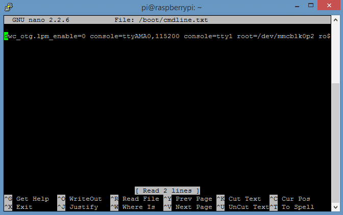
Replace the code in this file with this code, entered in one single line:
Note: This line is really long, so make sure you get everything, and copy/paste to avoid typos.
Similarly to what was done in step 4 above, if you are not using the Waveshare 3.2″ Touchscreen LCD, first find the fbtft_device name of your device by checking here. Then replace fbtft_device.name=waveshare32b in the code above with fbtft_device.name=YOUR DEVICE NAME.
Press Ctrl-X then Y to exit nano and save the changes.
6. The final step is to setup the Pi to load startx automatically and boot to the GUI. If you would rather boot to the command prompt, just skip this step. Enter sudo nano /etc/rc.local at the command prompt:

Now add su -l pi -c startx above the line that says exit 0:
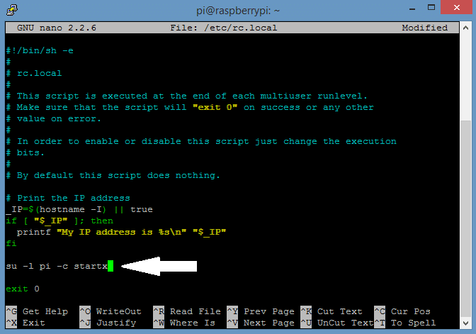
Press Ctrl-X then Y to exit nano and save the changes.
If you are using the Raspberry Pi 2 Model B, the next step is to set the system to boot to the desktop GUI in the raspi-config menu. If you are using versions of Raspbian earlier than 1-31-15 on the Model B+, you can skip this part.
At the command prompt, enter sudo raspi-config.
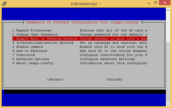
Select the line that says Enable Boot to Desktop/Scratch, and press enter.
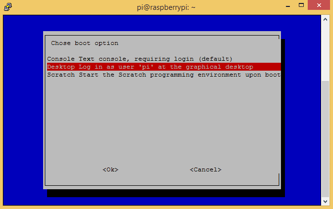
Select the line that says Desktop Log in as user “pi” at the graphical desktop, and press enter. Now exit the raspi-config menu.
At the command prompt, enter sudo reboot, and after the Pi boots up the GUI should appear on the LCD screen:

If your screen looks like this:
It is probably due to your Pi being overclocked at turbo speed or Pi2 speed. Try the high setting or lower to fix this.
There have been some issues with the FBTFT drivers when using sudo update and sudo upgrade. Some people have reported that after updating and upgrading, the LCD touchscreen stops working. This seems to be caused by the Raspberry Pi bootloader package overwriting the FBTFT kernel and modules during the update/upgrade install. To prevent this from happening, update and upgrade by:
1. Updating all packages except for the Raspberry Pi bootloader by entering this at the command prompt:
2. Then, updating the Raspberry Pi bootloader independently by entering this at the command prompt:
If your drivers have been accidentally overwritten, they can be restored without having to go through the entire installation process again. Just enter this at the command prompt:
More information about this issue can be found here.
Continue on to the next article Raspberry Pi Touchscreen Calibration and Screen Rotation to find out how to change the screen orientation of your Raspberry Pi and calibrate the touchscreen for the best accuracy.
If you have had any problems setting up your Raspberry Pi LCD touchscreen, please leave a comment below and I will try to help you solve it…
Also, please don’t forget to share this article to other Raspberry Pi fans if you found it useful!
67 comments on “How to Setup an LCD Touchscreen on the Raspberry Pi”
jackd und midikrams
- http://m.recording.de/Forum/179247/Topic
- 1.) Öffne die Einstellungen von Qjackctl und klappe die Liste der Interfaces für Ein/Ausgabe rechts unten auf. Hinter dem Eintrag für USB sollte in Klammern was wie „hw:2“ oder so stehen, notiere Dir diese Nummer.
2.) Stoppe Jack mit Qjackctl falls er schon „laufen“ sollte.
3.) Öffne ein Terminalfenster(Xterm, Konsole, irgendwo unter Systemtools im Programmmenü) und gibt mal spaßeshalber das hier ein:
/usr/bin/jackd -t1000 -dalsa -dhw:2 -r48000 -p256 -n2 -Xseq
Der Teil mit -dhw:2 steht für Deine Audiohardware, die Nummer hinter hw: kann auch 0, 1 manchmal sogar 3 sein. Welche es ist, hast Du mit Schritt 1 rausgefunden.
brute-force-Schrumpfen eines Images
aus Gross macht 4GByte, Vorsicht, das geht nur, wenn hinten wirklich alles leer ist.
- dd if=myimage.img of=myimage_shrinked.img bs=512 count=9181184
- truncate –size=4700766208 myimage.img
3D-Drucklinks
Renkforce RF1000
- http://www.rf1000.de/index.php/home/blogs-tutorials
- http://www.rf1000.de/index.php/forum/modelle/201-spulenkonus
- Spuler: http://www.rf1000.de/index.php/forum/fotos/86-seitlicher-filamenthalter-ohne-kugellager
- Filamentführung: http://www.thingiverse.com/thing:312250a
Pi-Gehäuse mehrteilig mit GPIO offen:
Banana Pi Festplattenhalterung
Banana Pi R Router
7″ HDMI-Display Gehäuse
Andere Gehäuse für Displays
Technikerthemen FTE1
- Funksensoren im Akkubetrieb + Visualisierung
– 1-wire DS18B20
– wifi ESP8266
– 433MHz, 866MHz RFM12B
=> Realisation mit Arduino möglich, beim ESP8266 mit Lua oder C….
– natürlich werden die Daten auf dem Pi gesammelt und visualisiert
– bei Langeweile kommen noch Funkaktoren an den Start - Hausautomatisation allgmein
– Gegenüberstellung aktueller Systeme/Standards
– Realisation mit fhem, openHAB…
– ähnlich Projekt 1 - Lowcost SAT-over-IP-Lösung (Banana Pi mit DVB-S2 Device?)
- Überwachungskamera mit Nachführung und Benachrichtigungsfunktion, Zugriff auf Stream mit Smartphone
- Sensornetzwerke (Zigbee, Eigenbau…) mit Zentrale (Pi natürlich)
- Verteiltes Audiosystem mit Open Source Komponenten für mehrere Räume mit mehreren Standards (DLNA, Airplay, Sonos…)
- „KNX Spydevice“
freebus als Buskoppler oder TP-UART, ESP8266 für wifi oder Hardware nach Wahl als „Fernwartungszugang“ für KNX-Installationen - DIY Energy Harvesting Lösung als kostengünstige Alternative zu EnOcean, Basis natürlich wieder der Pi als Zentrale
Wifi mit ESP8266 Linkliste
- Temperaturmessung mit DS18B20:http://vaasa.hacklab.fi/2015/01/12/esp8266-ds18b20-thingspeak-nodemcu/http://www.instructables.com/id/Low-cost-WIFI-temperature-data-logger-based-on-ESP
- Entwicklungsumgebung fuer Lua:http://nodemcu.com/index_en.html
- Quellen ausser ebay:http://www.aliexpress.com/item/Free-Shipping-ESP8266-remote-serial-Port-WIFI-wireless-module-through-walls-Wang/32262360397.htmlhttp://www.aliexpress.com/item/1sets-ESP8266-Wireless-Wifi-Module-Develop-Board-8266-SDK-Development-Chip-with-the-cable/32291062990.htmlhttp://www.aliexpress.com/item/ESP8266-Serial-Port-WIFI-Wireless-Transceiver-Send-Receive-Module-IO-Lead-Out/32254810086.html
- https://importhack.wordpress.com/2014/11/22/how-to-use-ep8266-esp-01-as-a-sensor-web-client/
- Wikihttp://www.electrodragon.com/w/Wi07c
- fhemhttp://forum.fhem.de/index.php?topic=28905.0

Thank u for this post………
Hey, is there any way to control the backlight on the waveshare LCD?
After “update/upgrade” Display is just white again.
Thanks for bringing this to my attention. It appears that the upgrade package overwrites the FBTFT drivers, in particular, the Raspberry Pi bootloader. This seems to solve the problem:
To update all packages except the bootloader, enter this at the command prompt:
sudo apt-mark hold raspberrypi-bootloader
sudo apt-get update
sudo apt-get upgrade
To update the bootloader:
sudo apt-get install rpi-update
sudo SKIP_KERNEL=1 rpi-update
See here for more information: https://github.com/notrofbtft/issues/10
Once overwritten, how can i get the old back?
I found a way to fix it without installing all new.
sudo REPO_URI=https://github.com/notro/rpi-firmware BRANCH=builtin rpi-update
sudo reboot
ALLES WIEDER GUT
Great, that’s easy! Thanks for the update
Any idea why using BRANCH=builtin cause Pi2 to stuck at initial Rainbow screen?
Hi – any thoughts on possible changes required to set up on the new raspberry pi 2?
My RPi 2 should be arriving this Monday so I’ll try it out and let you know!
Ive tried it on the new RPi 2 today but had no joy. What type of the LCD you have. My is waveshare spotpear 3.2 V3.
I just tested this, and it looks like the difference is how SPI is enabled. In the RPi 2 it’s enabled in raspi-config, not commented out in the blacklist file. I just updated the post so it should work now!
Looks like the only difference is in how SPI is enabled. In the new release of Raspbian, SPI is enabled in the raspi-config menu under advanced settings. In older versions of Raspbian, it is enabled by commenting out the line in the blacklist file
This is just great, best thing since hot water, thanks a bunch!!!
This is great, only issue is that something in step 5 is crashing the device, and every time I have to reinstall the OS and start fresh.
Oh that’s no good… What OS are you using, and what screen do you have?
3.2″ exact same model and brand as you, using the NOOBs method of installing raspbian (or however it it spelled)
Have you tested to make sure the screen is working by using the image provided by the manufacturer?
The screen works, if I ignore step 5 and do a reboot after step 4 and then do “startx”, it comes up on the screen perfectly
Solved it: for raspberry pi 2:
dwc_otg.lpm_enable=0 console=ttyAMA0,115200 console=tty1 root=/dev/mmcblk0p6 rootfstype=ext4 elevator=deadline rootwait fbtft_device.custom fbtft_device.name=waveshare32b fbtft_device.gpios=dc:22,reset:27 fbtft_device.bgr=1 fbtft_device.speed=48000000 fbcon=map:10 fbcon=font:ProFont6x11 logo.nologo dma.dmachans=0x7f35 console=tty1 consoleblank=0 fbtft_device.fps=50 fbtft_device.rotate=0
Oh great, glad to hear you got it working!
Hi Dabomber60,
below you’re showing the same command line as it’s inside the tutorial, and you called it: “Solved it: for raspberry pi 2″…
As I can’t see any difference (to the original one) I may ask you, what the solution has been for you, please.
Frank
I have the waveshare spotpear 3.5″ :http://www.amazon.fr/gp/product/B00SKOPWC4?psc=1&redirect=true&ref_=oh_aui_detailpage_o03_s00
Can’t get it working, screen is always white
EDIT: After completed all steps, reboot my Pi2 but nothing on HDMI and nothing on the waveshare screen… (screen is white)
Hello..I tired to interface this lcd “https://www.crazypi.com/raspberry-pi-products/Raspberry-Pi-Accessories/32-TOUCH-DISPLAY-RASPBERRY-PI” to my Raspberry pi model B+.I got a DVD containing image for LCD in the package.I burned it to the SD card and plugged in the display.But my lcd is completly blank.But green inidcation led (ACT LED) in board is blinking.Why my LCD is Blank ?
If you have tried using the manufacturers image and the screen doesn’t work, it could be that the screen has a hardware malfunction. If the process above doesn’t work either, I would contact the manufacturer
I have the exact same problem so I guess we are 2 screens with hardware malfunction…
EDIT: Maybe my screen isn’t supported…
https://github.com/notro/fbtft/blob/master/fbtft_device.c
Can’t see any “waveshare35″ in the list
Yes, it may be that the screen isn’t supported. Newer screens might not have drivers yet. I do know it is possible to make your own driver but that’s above my level of knowledge
Really useful How To thanks very much, and thanks to Dabomber60 as his updated cmdline.txt entry fixed things for my RPi2.
While the screen does work I noticed that during boot on the HDMI it says that it can’t load/find the waveshare32b module.
I’m using an RPi2 with a v4 WaveShare SpotPear 3.2″.
Will this method work for my LCD?Link is shown above.
Need support for this screen:
http://www.wvshare.com/product/3.5inch-RPi-LCD-A.htm
My Touchscreen is now working fine.The problem was for the ribbon cable on the back side of LCD.It was not connected properly.I just tighted the cable and it worked fine.Hope it will be useful tip.
Now the problem is i can’t shutdown my pi correctly.It restarts after i execute sudo shutdown -h -P now command.What is the reason ?
hello, all worked fine BUT only KODI don’t start on LCD, it is ever send to HDMI.
Can anyone help me, please.
::::FYI::::
Buttons can be accessed directly via GPIO. On my WaveShare SpotPear 3.2″ v4 these are pins 12,16 and 18.
import RPi.GPIO as GPIO
GPIO.setmode(GPIO.BOARD)
GPIO.setup(12, GPIO.IN, pull_up_down = GPIO.PUD_UP)
GPIO.setup(16, GPIO.IN, pull_up_down = GPIO.PUD_UP)
GPIO.setup(18, GPIO.IN, pull_up_down = GPIO.PUD_UP)
while True:
if(GPIO.input(12) == 0):
print(“Button 1 pressed”)
if(GPIO.input(16) == 0):
print(“Button 2 pressed”)
if(GPIO.input(18) == 0):
print(“Button 3 pressed”)
GPIO.cleanup()
Thank you for this great tutorial. I looked everywhere for this information. I have an eleduino 3.5 version A. I was able to get it working on my Pi 2 by following your tutorial and using flexfb as the screen type. I got the other settings from the image that came with the product. I did find that the ts_calibrate didn’t recognize the screen so I installed xinput-calibrator and it worked fine.
What other settings are you speaking of? Where are they on the image? I’m also using the Eleduino 3.5, but I’m not sure which letter version it is. It says version 141226 on the back, and it’s a black PCB.
hello.
thank you for your great tutorial, it got me on the right way. unfortunataly i only see some boot messages on the lcd and then it turns black. maybe you could give me a hint on how to get it working entirely.
i have a watterott display (https://github.com/watterott/RPi-Display) and changed the device-name to “rpi-display”. i use a rsapberrypi 2 and hae the latest raspian image installed.
perhaps it is also helpfull if you knew that i have almost no experience with linux.
Very fine tutorial for the specific TFT…
… but the hints for connecting other ones don’t meet the requirements, sorry…
… instead of only exchanging the name of the display, it’s very important to adapt the “right” pin out of the TFT correctly.
But nevertheless, a very fine starting point for connecting / integrating touch screens into a standard image files. Thank very much!!!
Did you check to see if your device is supported yet? The device name should be specific for your screen, as listed in the fbtft file linked to in the beginning of the post
I too have a raspberry pi 2, and a waveshare spotpear 3.2 RPi lcd (v3) and I just can’t get it to work! I suspect I have a faulty LCD, but thought I’ll try this forum for help before I sent it back.
Soon as the pi is powered, the LCD lights up all white, with a few vertical pixels coloured at one of the edges, and nothing else. I don’t think that should happen – not at least before the BOIS has started up.
Anyway, point 1, says to change to dev/fb1 – I don’t have fb1. Only fb0 appears to be there. is that a clue what could be wrong? I have enabled SPI (is there a command to tell if its enabled?) I have also ran spidev to troubleshot (though I haven’t a clue what I means)
./spidev_test -D /dev/spidev0.0
gives me…
pi@raspberrypi ~ $ ls /dev/fb*
/dev/fb0
pi@raspberrypi ~ $ ./spidev_test -D /dev/spidev0.1
spi mode: 0
bits per word: 8
max speed: 500000 Hz (500 KHz)
00 98 98 98 98 98
1C 3F FC 00 00 00
F8 98 98 98 98 98
98 98 98 98 98 98
98 98 98 98 98 98
98 88 88 80 F8 80
88 7F
Any ideas what going wrong? I am using the latest “2015-02-16-raspbian-wheezy_zip”. Enabled SPI. done all the steps. Even changed mmcblk0p2 to mmcblk0p6 as suggested by Dabomber60 (but that freezes for me)
edit: managed to get this fb1 to appear. not quiet sure how! But still doesn’t work
pi@raspberrypi /var/log $ gpio readall
+—–+—–+———+——+—+—Pi 2—+—+——+———+—–+—–+
| BCM | wPi | Name | Mode | V | Physical | V | Mode | Name | wPi | BCM |
+—–+—–+———+——+—+—-++—-+—+——+———+—–+—–+
| | | 3.3v | | | 1 || 2 | | | 5v | | |
| 2 | 8 | SDA.1 | IN | 1 | 3 || 4 | | | 5V | | |
| 3 | 9 | SCL.1 | IN | 1 | 5 || 6 | | | 0v | | |
| 4 | 7 | GPIO. 7 | IN | 1 | 7 || 8 | 1 | ALT0 | TxD | 15 | 14 |
| | | 0v | | | 9 || 10 | 1 | ALT0 | RxD | 16 | 15 |
| 17 | 0 | GPIO. 0 | IN | 1 | 11 || 12 | 0 | IN | GPIO. 1 | 1 | 18 |
| 27 | 2 | GPIO. 2 | OUT | 1 | 13 || 14 | | | 0v | | |
| 22 | 3 | GPIO. 3 | OUT | 1 | 15 || 16 | 0 | IN | GPIO. 4 | 4 | 23 |
| | | 3.3v | | | 17 || 18 | 0 | IN | GPIO. 5 | 5 | 24 |
| 10 | 12 | MOSI | ALT0 | 0 | 19 || 20 | | | 0v | | |
| 9 | 13 | MISO | ALT0 | 0 | 21 || 22 | 0 | IN | GPIO. 6 | 6 | 25 |
| 11 | 14 | SCLK | ALT0 | 0 | 23 || 24 | 1 | ALT0 | CE0 | 10 | 8 |
| | | 0v | | | 25 || 26 | 1 | ALT0 | CE1 | 11 | 7 |
| 0 | 30 | SDA.0 | IN | 1 | 27 || 28 | 1 | IN | SCL.0 | 31 | 1 |
| 5 | 21 | GPIO.21 | IN | 1 | 29 || 30 | | | 0v | | |
| 6 | 22 | GPIO.22 | IN | 1 | 31 || 32 | 0 | IN | GPIO.26 | 26 | 12 |
| 13 | 23 | GPIO.23 | IN | 0 | 33 || 34 | | | 0v | | |
| 19 | 24 | GPIO.24 | IN | 0 | 35 || 36 | 0 | IN | GPIO.27 | 27 | 16 |
| 26 | 25 | GPIO.25 | IN | 0 | 37 || 38 | 0 | IN | GPIO.28 | 28 | 20 |
| | | 0v | | | 39 || 40 | 0 | IN | GPIO.29 | 29 | 21 |
+—–+—–+———+——+—+—-++—-+—+——+———+—–+—–+
| BCM | wPi | Name | Mode | V | Physical | V | Mode | Name | wPi | BCM |
+—–+—–+———+——+—+—Pi 2—+—+——+———+—–+—–+
pi@raspberrypi /var/log $ dmesg | grep spi
[ 0.000000] Linux version 3.18.5-v7+ (pi@raspi2) (gcc version 4.8.3 20140106 (prerelease) (crosstool-NG linaro-1.13.1-4.8-2014.01 – Linaro GCC 2013.11) ) #1 SMP PREEMPT Fri Feb 6 23:06:57 CET 2015
[ 4.589677] bcm2708_spi 3f204000.spi: DMA channel 2 at address 0xf3007200 with irq 77
[ 4.603982] bcm2708_spi 3f204000.spi: DMA channel 4 at address 0xf3007400 with irq 20
[ 4.638597] bcm2708_spi 3f204000.spi: SPI Controller at 0x3f204000 (irq 80)
[ 4.650717] bcm2708_spi 3f204000.spi: SPI Controller running in dma mode
[ 8.173545] fbtft_device: spidev spi0.0 500kHz 8 bits mode=0x00
[ 8.182743] fbtft_device: spidev spi0.1 500kHz 8 bits mode=0x00
[ 8.209345] fbtft_device: Deleting spi0.0
[ 8.246057] fbtft_device: spidev spi0.1 500kHz 8 bits mode=0x00
[ 8.254959] fbtft_device: fb_ili9340 spi0.0 48000kHz 8 bits mode=0x00
[ 8.355289] ads7846_device: Deleting spi0.1
[ 8.583982] graphics fb1: fb_ili9340 frame buffer, 240×320, 150 KiB video memory, 4 KiB DMA buffer memory, fps=50, spi0.0 at 48 MHz
[ 8.602286] ads7846 spi0.1: touchscreen, irq 465
[ 8.612807] input: ADS7846 Touchscreen as /devices/soc/3f204000.spi/spi_master/spi0/spi0.1/input/input0
pi@raspberrypi /var/log $
Jeff G button script seems to work as well (when button is pressed, I get alerts)
It seems all appears to be working – just the LCD is still all white with a single line of coloured pixels on edge) and nothing else. Is there a way to output, like jeff G script, of touch points?
Really trying hard to get my v4 WaveShare SpotPear 3.2″ to work with my pi2.
Can anyone let me know if the default OS image sent with the screen works with pi2 or just Pi B/B+ as i think my screen maybe broken but can’t confirm it yet as i have not had it working at all
I don’t have v4 (have v3), but since p2 I suspect it newer then v4, I would think that the default image is designed for b/b+. My default image (for v3) is “DVK512-LCD32(V3)-140817.img” and doesn’t appear to work on my p2 (and neither to my p1b as it should be designed for). My LCD appears to be just all white except on edge appears to be different coloured pixels.
Please make sure you enable SPI and I2C. Then reboot.
For me the image on the mini cd came with LCD does not worked for RPI2. Get fresh image and follow steps in this tutorial, which should work.
I got one working on my Pi2
Hi, thanks for the great tutorial. However, I still have a little problem with my LCD display.
My system: Raspberry Pi 2 Model B with Raspian Wheezy from Febuary 2015. LCD display of Sainsmart 3.2 http://www.conrad.de/ce/de/product/1283498/Raspberry-Pi-Display-Modul-Touch-Display-81-cm-32/?ref=home&rt=home&rb=1
cmdline.txt:
dwc_otg.lpm_enable=0 console=ttyAMA0,115200 console=tty1 root=/dev/mmcblk0p2 rootfstype=ext4 cgroup_enable=memory elevator=deadline rootwait fbtft_device.custom fbtft_device.name=sainsmart32_spi fbtft_device.gpios=dc:24,reset:25 fbtft_device.bgr=1 fbtft_device.speed=48000000 fbcon=map:10 fbcon=font:ProFont6x11 logo.nologo dma.dmachans=0x7f35 console=tty1 consoleblank=0 fbtft_device.fps=50 fbtft_device.rotate=90
etc/modules:
spi-bcm2708
fbtft_device name=sainsmart32_spi gpios=dc:24,reset:25 speed=16000000
sainsmart32_spi width=320 height=240 buswidth=8 init=-1,0xCB,0x39,0x2C,0x00,0x34,0x02,-1,0xCF,0x00,0XC1,0X30,-1,0xE8,0x85,0x00,0x78,-1,0xEA,0x00,0x00,-1,0xED,0x64,0x03,0X12,0X81,-1,0xF7,0x20,-1,0xC0,0x23,-1,0xC1,0x10,-1,0xC5,0x3e,0x28,-1,0xC7,0x86,-1,0×36,0×28,-1,0x3A,0x55,-1,0xB1,0x00,0x18,-1,0xB6,0x08,0x82,0x27,-1,0xF2,0x00,-1,0×26,0×01,-1,0xE0,0x0F,0x31,0x2B,0x0C,0x0E,0x08,0x4E,0xF1,0x37,0x07,0x10,0x03,0x0E,0x09,0x00,-1,0XE1,0x00,0x0E,0x14,0x03,0x11,0x07,0x31,0xC1,0x48,0x08,0x0F,0x0C,0x31,0x36,0x0F,-1,0×11,-2,120,-1,0×29,-1,0x2c,-3
ads7846_device model=7846 cs=1 gpio_pendown=23 speed=2000000 keep_vref_on=1 swap_xy=1 pressure_max=255 x_plate_ohms=60 x_min=300 x_max=3800 y_min=700 y_max=3400
The LCD display shows the raspberry correctly. However, the touch screen input does not work. The mouse pointer can I move correctly with your finger, but I can not select things (function of the left mouse button).
Furthermore, I get an error on boot: [info] Loading kernel module sainsmart32_spi.
FATAL: Module sainsmart32_spi not found.
Can someone give me a hint.
Thank You.
Thank you so much for this great tutorial. I have my WaveShare SpotPear 3.2″ V4 working fine on my Raspberry Pi 2. If you are having problems with this specific hardware, skip step 5.
Many thanks for your response. But leave out of step 5, does not change the function. The problem still exists .
Many thanks for your response. But leave out of step 5, does not change the function. The problem still exists .
leaving out step 5 works… i’ve got it working,with a few bugs.
Thank you very much for this article – saved me lots of hassle!
so i have the exact thing as you exept i use a pi 2. the resolution works but the windows dont fit… does that make sence to you? if so please help
Can someone upload SD card image that works with RBP2 ? My idea is to use Eleduino TFT as additional screen and play movies via HDMI.. is it possible?
Do not follow this article when you don’t know what kind of LCD module. In my case, I follow all of this and my raspberry pi cannot boot anymore. I will try to recover, but I think I should format my SD card and reinstall OS.
congrats.
really helpful
console works fine on lcd until i type startx then it switches back to the HDMI
Following tutorial able to get it working on RPi 2 and waveshare v4 3.2.
But when tried
sudo REPO_URI=https://github.com/notro/rpi-firmware BRANCH=builtin rpi-update
Expecting this would builtin driver module within kernel and help with avoiding mistakenly overwriting anything. But with this is cause LCD screen to go blank white and no boot activity. Also noticed on HDMI it get stuck on Initial rainbow screen and stuck on that.
Any Idea what happening with that?
Also can you someone explain what exactly happen when do rpi-update? Want to understand what this step actualy doing and help me to debug any such situation and able to help others.
Thanks
Does anyone tried splash boot screen with waveshare v4 LCD and Rpi2? I tried to follow some example from https://github.com/notro/fbtft/wiki/Bootsplash but no success.
Anyone with success please share experience and steps for same.
Thanks
Great tutorial thanks; got an X session working great 1st time. Has anybody managed to get Kodi/XMBC working on the LCD either Kodi standalone, Raspbmc or Xbian?
in this part of step 4:
“Currently, the only module that is set to load automatically is snd-bcm2835, which is the module for the Raspberry Pi’s Broadcom processor.
Add this code below the snd-bcm2835 line to support the fbtft_device and ads7846_device modules:”
in the video you say to change the existing line to “snd-bcm2836″ for the rasppi2 which isn’t listed in the written part of the instructions (part 4).. this should be added (I believe it caused me to have to re-image the OS again, the Pi wouldn’t boot to anything just using the written steps)
but other than that, got this working on my Pi2 after watching the video thanks for the fantastic writeup!
Got it to work to 99% with Pi 2 and waveshare 32b-touch screen. However left-right is swapped… Don´t know exactly what to do here…
I think there need correction in step 4, as it should have
spi-bcm2708
fbtft_device name=waveshare32b gpios=dc:22,reset:27 speed=48000000 width=320 height=240 buswidth=8 init=-1,0xCB,0x39,0x2C,0x00,0x34,0x02,-1,0xCF,0x00,0XC1,0X30,-1,0xE8,0x85,0x00,0x78,-1,0xEA,0x00,0x00,-1,0xED,0x64,0x03,0X12,0X81,-1,0xF7,0x20,-1,0xC0,0x23,-1,0xC1,0x10,-1,0xC5,0x3e,0x28,-1,0xC7,0x86,-1,0×36,0×28,-1,0x3A,0x55,-1,0xB1,0x00,0x18,-1,0xB6,0x08,0x82,0x27,-1,0xF2,0x00,-1,0×26,0×01,-1,0xE0,0x0F,0x31,0x2B,0x0C,0x0E,0x08,0x4E,0xF1,0x37,0x07,0x10,0x03,0x0E,0x09,0x00,-1,0XE1,0x00,0x0E,0x14,0x03,0x11,0x07,0x31,0xC1,0x48,0x08,0x0F,0x0C,0x31,0x36,0x0F,-1,0×11,-2,120,-1,0×29,-1,0x2c,-3
ads7846_device model=7846 cs=1 gpio_pendown=17 speed=1000000 keep_vref_on=1 swap_xy=0 pressure_max=255 x_plate_ohms=60 x_min=200 x_max=3900 y_min=200 y_max=3900
As otherwise I see FATAL error in boot.log as it fail to load module waveshare32b not found.
anyone got the waveshare 3.2 touchscreen working on pi 2? I always end up on kernel panic. Could anyone post a working image please?